| SECTIONS
 The construction of sections is similar to the elevations, except that structural parts, such as foundation walls, beams, joists, walls, rafters, etc., and the construction of concealed details, such as cornices, soffits and eaves, are observed, measured and drawn. The construction of sections is similar to the elevations, except that structural parts, such as foundation walls, beams, joists, walls, rafters, etc., and the construction of concealed details, such as cornices, soffits and eaves, are observed, measured and drawn.
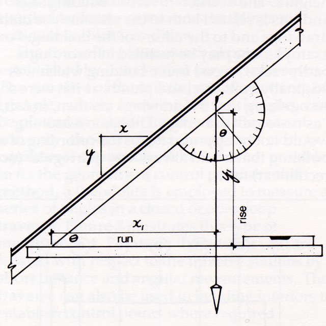
The measurement of roof slopes can be made by measuring the rise and the run or by using a plumb bob and protractor (see Figure 5). The sizes of structural members should be given in actual dimensions (not nominal, as in 2 x 4, etc.) and the spacings should be measured at least frequently enough to establish the pattern (e. g. 57 x 190 joists @ 450 mm ± 8 mm) with exceptions noted. The determination of floor and wall construction may require the cutting of inspection traps; however, the necessity for doing so should be carefully considered and the location given equally detailed attention.
Figure 5
Several methods of measuring roof slopes: by measurement of rise and run x:y = x1:y1, or by angular measurement using plumb bob and protractor.
RECORDING OF DETAIL
Detail will include windows; doors; hardware; moldings, such as baseboard, wainscotting, picture rails, cornices and eavestroughs; mantelpieces; panelling; exterior cladding and trim; eave and soffit details; brackets; and miscellaneous structural and decorative details. They are recorded by direct measurement (often with the aid of a plumb line or level) and referenced to gridlines where these are used. In addition, the following special techniques are used: |
|
- Profile Measurements: gauging devices based on sliding metal laminations or pins are available. When carefully pressed against the profile of a molding, they will duplicate the shape. It is best to reproduce this shape on a piece of stiff paper which is then cut out and checked against the original. Profiles can also be obtained by fitting strips of flexible metal - lead or aluminum foil - to the contours of the surface. An accurate method of obtaining the profile is at an exposed end or, open joint. Care should be taken to measure a representative sample that has not been damaged by wear or obscured by excessive paint.
- Rubbings: outlines of inscriptions, low-relief ornamental features, hardware, fretwork, etc., can be quickly obtained by overlaying a piece of paper and rubbing with a crayon. The image so produced is then traced onto drafting paper.
- Measurements of Offsets: this system is used for delineating complex and/or curved elements. A fixed baseline is established near the object in the same plane as the face to be measured. Perpendiculars are erected at uniform or convenient intervals and the distance to the points on the curve from the baseline are recorded. The baseline may be vertical - for example, a plumb line (see Figure 6) - or horizontal or sloped.
|