| HAND MEASUREMENT
 The objective of measurement is to obtain those dimensions which, when plotted to scale, will produce the views (plans, elevations and sections) that will accurately and completely delineate the building. To do this requires a knowledge of both basic drafting principles and elementary survey techniques. The objective of measurement is to obtain those dimensions which, when plotted to scale, will produce the views (plans, elevations and sections) that will accurately and completely delineate the building. To do this requires a knowledge of both basic drafting principles and elementary survey techniques.
The first step is to define the overall form of the plan, i.e., the shape of the exterior perimeter and the interior spaces in horizontal section. Subsequently, the elevations and sections are produced. Detail is filled in on all views as they are completed.
There are two distinct approaches in current practice to the problem of establishing the accurate geometry of the plan of a building. The first method called the grid system, involves the establishment of the rectilinear grid through and around the building. Measurements are taken from points on the building to the resultant gridlines and from this information the building plan is plotted. The alternative approach employs one or more survey techniques to accurately define the position of a number of well chosen points on the building itself. Since no regular grid is used 1 have called this system the direct method. Further detail and a discussion of the merits and drawbacks of each system are as follows.
|
|
THE GRID SYSTEM
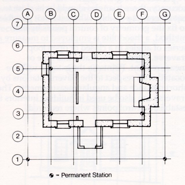
This system can be applied to any structure; however, its most advantageous application is to buildings of irregular geometry and/or materials, for example, primitive structures or buildings in ruins. The gridlines, usually spaced at 1500 mm (5'0") on centre, are laid out using a theodolite and tape measure, and the points of intersection are marked with survey tacks set in stakes (exterior) or on the building itself (interior). A typical set-up is shown in Figure 1. Measurements can be made to string or chalk lines set between these points or to the sight line of a theodolite aligned on a gridline. Measurements are taken to the wall surfaces at intervals sufficiently closely spaced to define the shape of the walls (usually at the grid module spacing) and at corners, door frames, windows, and all other features required to produce the plan. These measurements, when plotted, will unambiguously define the building geometry, and thickness of walls and other inaccessible spaces will be evident.
Figure 1
Typical grid layout in plan. The gridline spacing is usually set at 5'-0" or 1500 mm. The system is positioned for convenience in measuring to building faces
|