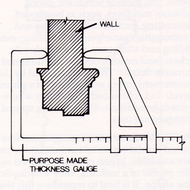
Figure 3
One method of measuring wall thickness. Another method is by summation of component parts.
 3.The exterior plan of the building is plotted from survey measurements and it is laid over the interior plan. The exterior wall thicknesses apparent in this superimposition are checked against those actually measured in the field. At this point, discrepancies must be resolved, by checking measurements and possibly by taking additional ones. When the residual distributed error is equal or less than the acceptable tolerance, the plan can be considered to be resolved. 3.The exterior plan of the building is plotted from survey measurements and it is laid over the interior plan. The exterior wall thicknesses apparent in this superimposition are checked against those actually measured in the field. At this point, discrepancies must be resolved, by checking measurements and possibly by taking additional ones. When the residual distributed error is equal or less than the acceptable tolerance, the plan can be considered to be resolved.
THE DIRECT METHOD
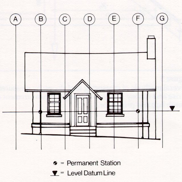
Measurement procedures for the drawing of these views are similar in both the grid and direct systems. In the grid system, horizontal distances are measured to the gridlines and vertical distances are measured to a datum (level line) that has been established around the building using a surveyor's level (see Figure 4). |
|
Typically, the vertical measurements are taken to floors, ceilings, window and door sills and heads, and to ground level, foundation walls, plinths, eaves, soffits and ridges. In direct measurement surveys, if the floor is reasonably level, it can be used as the level reference datum. On the exterior, the water table or plinth is used for the same purpose. If the floors are not level, a level datum can be established as in grid surveys. If the walls, columns, etc., are tilting significantly, then plumb lines can be used to provide reference lines for measurement of horizontal distances at various heights. The decision to record building sags and tilts is related both to the ultimate use of the drawings and to the nature of the building. For example, one may be justified in recording a badly racked wood frame building which was originally built level and plumb, as if it were so, recognizing that the drawings are then, in fact, ,,as restored" drawings. The same reasoning would not be appropriate for the recording of a building that is and always was of irregular (non rectilinear) form.
Figure 4
Typical grid layout in elevation. The use of a level datum line is not restricted to grid type surveys. |