|
 Although the grid system appears to be simple and scientific in its method, it suffers from several real disadvantages. First, the laying out of the grid is an extra step which must be carried out with great accuracy (+5mm), as must the measurements, themselves. The system is not workable as an approximate approach. Secondly, the number of individual measurements is greatly multiplied with the grid system. The combination of these factors makes the method slow but accurate and still the best choice for ruinous sites. Although the grid system appears to be simple and scientific in its method, it suffers from several real disadvantages. First, the laying out of the grid is an extra step which must be carried out with great accuracy (+5mm), as must the measurements, themselves. The system is not workable as an approximate approach. Secondly, the number of individual measurements is greatly multiplied with the grid system. The combination of these factors makes the method slow but accurate and still the best choice for ruinous sites.
THE DIRECT METHOD
The direct method employs measurements to points on the building surfaces as a means of defining overall form. These points, whose relative positions are established, are referred to here as "control" points. This system is appropriate for the recording of buildings with reasonably uniform continuous surfaces as typified by frame or masonry buildings in reasonably intact condition.
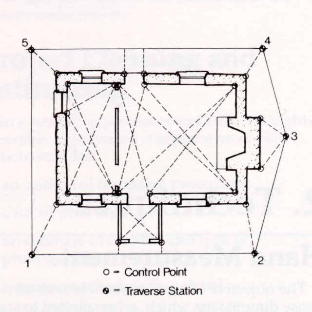
The controlling framework of points is established by one or more survey techniques. The simplest of these is the use of a network of triangles which, knowing the side lengths, can be plotted as "rigid" figures. For the sake of accuracy, these triangles should be as close to equilateral as possible. Where it is not possible to fix the geometry of control points by this method, a theodolite is employed to measure a series of angles in a closed or open loop traverse. Figure 2 illustrates this type of measurement. Points on the exterior wall are located with respect to the traverse stations by short distance and angular measurements. The traverse can also be used in building interiors to establish control points where required. |
|
Figure 2
Typical horizontal control points for direct measurement. Internal control points are established by triangulation and external control points by angle and distance measurements from a surveyed traverse. The two are correlated by measurement of wall thicknesses.
The drafting of floor plans by the direct system involves the fitting of interior and exterior dimensions and wall thicknesses into a coherent whole. The following description of the process is offered:
1.Each room has been measured and triangulated and its shape accurately drafted on individual sheets of tracing paper at a sufficiently large scale (normally 1:25). The location of all openings (doors, windows) is accurately plotted.
2.The internal and external wall thicknesses have been measured at all accessible points, e.g. at openings (see Figure 3). It may prove necessary to obtain additional wall thicknesses by drilling, inspection traps, comparison of construction details or by survey methods. Using the wall thicknesses and the position of openings, e.g. doors, windows etc., the individual room tracings are superimposed and aligned to produce an overall interior floor plan. Overall interior dimensions, taken wherever feasible, are used to check the overall plan. |