PWGSC National CADD Standard
3.0 PWGSC Computer Aided Drafting Standard
This section describes the general PWGSC Computer Aided Drafting Standard. Specific instructions can be added in the context of a request for proposal.
3.1 File Presentation
Files presented must conform to the following rules:
- A drawing must be purged of all definitions that are not used, such as layer names, text styles, dimension styles, layer filters, and blocks.
- A drawing must not contain any object definitions without geometry, such as empty text or blocks without objects.
- No objects should reside on layer "0" or "DEFPOINTS" except for objects contained in a block definition and dimensions. Use the "Plot/Non plot" layer property instead of the Defpoints layer.
- A drawing must not contain errors that are detectable using the Audit command.
- Drawings are to be modelled at full scale (real-world units) in model space, with text, symbols, hatch patterns, and line widths adjusted by the required scale factor.
All presented files must also adhere to the following rules of best practice:
- When appropriate to the type of drawing, lines must be drawn in an orthogonal mode.
- All vector endpoint intersections must be drawn with closed corners.
- The drawing must be saved with properly formatted Page Setup (Paper Size, Plot Style, Plot Area, Plot Scale, etc.). The main layout must be active and all the viewports adjusted and locked to the correct scale.
3.2 Layering Standard
All digital CADD files must follow the PWGSC Layering Standard. The standard facilitates data management by using a layering structure and naming convention to organize the drawing data in the CADD files into related data groups.
See Annex A – CADD Layers for the complete Standard Layer List.
See Annex B – Layer Field Descriptions for the abbreviations and descriptions lists used to create layer names.
3.2.1 Sorting Graphic Data into Related Data Groups
Layers are used to sort the graphical data types depicted by the line work into related data groups. (They are not intended for use in sorting line weights, line types, colours, or other schemes.)
Layering is the only way to identify what the entities on a graphical screen represent without resorting to annotations. For example, it answers questions such as whether a rectangle represents a building outline, a concrete pad, a storage tank, or whether it is an annotation box. All digital CADD files must follow the PWGSC Layering Standard to create the appropriate layers to accommodate the grouping of related data.
To simplify the layering, drawing data can be broken into two major groupings: principal data and supporting data. The level of complexity and number of layers required for the two groups are significantly different.
3.2.2 Principal Data
Principal data is contained mainly in the plan views of the facility, i.e., the base plan, floor plan, site plan, etc.
This type of data requires strict adherence to layer naming and proper grouping of data. The line work used to depict facility components must always be drawn using the most up-to-date and accurate information available. Line work depicting objects must be placed in the proper standard layer according to the data type being represented. For example, in a floor plan, the walls, doors, windows, and bathroom fixtures must be grouped under separate layers.
3.2.3 Supporting Data
Supporting data is made up of sections, details, elevations, schedules, legends, and title blocks, etc.
This type of data requires minimal layering breakdown. Line work in a detail representing different components does not need to be placed in separate layers. For example, a building construction detail can be drawn with foundation wall, frame wall, floor, and roof line work in a single layer, although the dimensions, annotation, and hatching should be separated.
3.2.4 Layering Naming Convention
Layering of CADD information must adhere to the layering naming convention described in this section.
The layer is the basic tool for organizing and managing graphic information. Layers are used to sort graphic objects into groupings of related data. PWGSC has developed a modular, alphanumeric layer nomenclature format designed to sort graphic data in a specific manner.
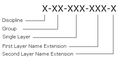
The layer name format consists of five fields separated by hyphens.
- The first three fields—Discipline, Group, and Single Layer—are mandatory.
- The last two fields—First Layer Name Extension and Second Layer Name Extension—are optional fields that allow a more precise data identification where necessary.
Text description of 3.2.4 Layer Name Convention is available on a separate page.
See Annex A – CADD Layers for a list of the most frequently used layer names and their descriptions.
See Annex B – Layer Field Descriptions for a complete list of the field abbreviations and descriptions for the last four of the five fields of the layer name structure.
Two-field layer names (X-XX) can only be used under special conditions and must have PWGSC approval.
Discipline Field X-XX-XXX
The Discipline field identifies the discipline responsible for the layer content. Where an object cannot be associated with a specific discipline, or is applicable to all disciplines, the special abbreviation of "G" may be used to indicate "General Information."
Discipline Field Abbreviations List:
- A: Architecture
- B: Bridges and Dams Engineering
- C: Civil Engineering, Site Design, and Landscape Architecture
- E: Electrical Systems
- G: General Information
- H: Mechanical
- I: Interior Design
- L: Legal Surveys
- M: Marine
- R: Real Property Space Management
- S: Building Structure
Group Field X-XX-XXX
The Group field identifies groupings of common types of drawing information relevant to each discipline. The Group abbreviations defined for each discipline are listed in the Standard Layer List in Annex A – CADD Layers. In addition, there are some common Group abbreviations defined for use with all disciplines for supporting graphic data such as sections, details, and others. Annex B – Layer Field Descriptions contains a complete list of all Group abbreviations and their descriptions.
Examples of common Group field abbreviations:
- GL: Global
- GR: Grid
- PL: Plan
- SC: Schedules
Single Layer Field X-XX-XXX
The Single Layer field subdivides the classifications to identify each layer more precisely. Single Layer abbreviations allow information pertaining to Physical Properties, Materials, Graphics, Text and discipline related data such as building systems to be included. The Single Layer abbreviations are listed in the Standard Layer List in Annex A – CADD Layers and Annex B – Layer Field Descriptions.
First Layer Name Extension (Optional) X-XX-XXX-XXX-X
The First Layer Name Extension, like the Single Layer field, allows information pertaining to Physical Properties, Materials, Graphics, Text and discipline related data to be included. The extensions use the same abbreviations as the Single Layer field. They may be used with any valid layer from the Standard Layer List. They may also be used as a Single Layer field value where appropriate.
Examples of common Single Layer and First Layer Name Extension abbreviations for all disciplines: (See Annex B – Layer Field Descriptions for a complete list).
Physical Properties:
- ABV: Above ground, above grade
- EME: Emergency
- EQP: Equipment
- EXT: Exterior
- HOR: Horizontal
- INT: Interior
- NOD: Node, horizontal reference point
- OPN: Openings
- RET: Return
- SUP: Supply
- UND: Underground, below grade
- VER: Vertical
Materials:
- ASP: Asphalt
- BLK: Block
- BRK: Brick
- CON: Concrete
- CRP: Carpet
- FIN: Finishes
- GRV: Gravel
- INS: Insulation
- PLA: Plastic
- STL: Steel
- STO: Stone
- TIL: Tile
- TIM: Timber
Graphics:
- 3DM: 3D model components of 2D symbols
- CLR: Colours
- DIG: Digitized or vectorized from scanned image
- HAT: Hatching
- LIN: Line work
- OLN: Outlines
- PRO: Profiles
- SPC: Special
- SYM: Symbols
- TAB: Tables
- TMP: Temporary
Texts:
- ATT: Attributes
- DIM :Dimensions
- IDN: Identification numbers or names
- SPT: Spot elevations
- TXT: Annotation, Text, detail notations, bubbles, graphic scales
Second Layer Name Extension (Optional) X-XX-XXX-XXX-X
The Second Layer Name Extension allows information pertaining to Geometry, Construction, Status, Second Language, and Numerical Options to be included. The extensions may be used with any valid layer from the Standard Layer List. Annex B – Layer Field Descriptions contains a complete list of all Second Layer Name Extension abbreviations and their descriptions.
Valid Layer Name Formats:
Four variants of the layer name format will be accepted, as indicated below:

Text description of Valid Layer Name Formats is available on a separate page.
Free Text Examples:
Add an underscore character at the end of a valid layer name to append free text to the layer name.
- M-SN-SPT_-1.0: Soundings at -1.0 m depth
- M-SN-HWL_14 January 1990: High Water Line on a specific date
Existing Floor Plan Examples:
Where plans are specifically titled "New" (or "Existing"), the "N" (or "E") Second Layer Name Extension modifier indicating the construction status may be omitted, but all disparate construction status extensions must be included.
- A-WL-INT-N: Architecture - Wall - Interior - New
- A-WL-INT-X: Architecture - Wall - Interior - Remove
- A-WL-OLN: Architecture - Wall Outline - Exterior ("Existing" implied)
- A-DR-INT: Architecture - Door - Interior ("Existing" implied)
- A-DR-INT-N: Architecture - Door - Interior - New
- A-WD-EXT: Architecture - Window - Exterior ("Existing" implied)
Symbols Examples:
When a symbol is placed to represent an object, it must be placed in a symbols layer.
- E-SD-SYM: Electrical - Site Distribution - Symbols (Power poles, luminary, etc.)
- G-GL-SYM: General - Global - Symbols (Key plans, north arrow, bar scale, etc.)
Detail Examples:
Supporting data such as dimensions, annotation, and hatching should be separated as indicated in the examples below. Colour should be set "Bylayer" for the majority of the entities in a layer and specifically where necessary to obtain varying line weights in that layer.
- G-DT-LIN: General - Detail - Line work (Wall, floor and roof line work)
- G-DT-TXT: General - Detail - Text (Annotations, title, graphic scale, etc.)
- G-DT-DIM: General - Detail - Dimensions
- G-DT-HAT: General - Detail - Hatching (Insulation, wood grain, etc.)
Schedule Examples:
- A-SC-LIN: Architecture - Schedule - Line work (Schedule grid or Line work)
- A-SC-TXT: Architecture - Schedule - Text (Schedule data, annotation)
Plan Views Examples:
Supporting data can also appear on plan views.
- H-PL-TXT: Mechanical - Plan - Text (Titles, graphic scale, annotation bubbles)
- S-PL-DIM: Structural - Plan -Dimensions
3.2.5 Colour Assignment Standard: Layer Colours and Pen Weights
Colour is to be used as a method of defining line weight to the plotter. Layers must be assigned appropriate colours and entities should be created with colour "Bylayer" where possible, except as provided for in the creation of symbols. If a CTB is provided by PWGSC, it must be used.
Suggested Line Weight Settings:
Extra Thin - 0.10 mm
HatchingThin - 0.15 to 0.25 mm
Dimension Lines
Centre Line
Intermediate Contour Lines
Leader and Extension
Phantom Lines
Grid LinesMedium - 0.30 mm to 0.50 mm
Hidden Lines
Index Contour Line
Text Normal (0.3 mm)
Text - Sub Headings (0.5 mm)
Visible Object OutlinesThick - 0.70 mm
Cutting Lines
Match Lines
Reference Lines
Section Lines
Text - Titles/Major Headings
Viewing PlanesExtra Thick - 1.00 mm
Title Sheet Border
3.2.6 Provision for Creation of New Layers
Because the Standard Layer List (Annex A – CADD Layers) does not cover all possibilities, the layering standard provides for the ability to create new layer names for new objects as required.
As in the preceding example of E-SD-SYM, a quick look in the Standard Layer List under the Electrical Systems section would indicate that this layer name is invalid since it is not on the list. However, it is an acceptable layer name created by adding an existing First Layer Name Extension to an existing Discipline-Group abbreviation. The rules for creating new layer names are as follows:
- A proper standard layer name for the object must not already exist.
- Must follow the standard layer name format.
- Must use an existing Discipline abbreviation. (E-SD-SYM)
- Must use an existing Group abbreviation. (E-SD-SYM)
Must use an existing three-character Single Layer field abbreviation or First Layer Name Extension. (E-SD-SYM)
3.3 Block Standard
AutoCAD® blocks are used to group entities. Graphic blocks shall not be exploded. Blocks representing simple objects or simple symbols shall not contain nested blocks (blocks made of blocks). The use of groups is preferable when grouping blocks together, for example, a table with chairs around it. Most symbols should be created with linetype and colour “Byblock.” This allows complete control over the appearance of the symbol. By default a symbol will take on the properties of the layer it is placed on, but it can be changed to suit requirements independent of the layer settings.
There are two different ways of creating and inserting AutoCAD® blocks, depending on their complexity. The basic rules are as follows:
- Simple blocks with one data type, e.g., toilet fixtures, furniture:
- Create the block on layer "0."
- The block must be inserted on the proper layer, e.g., office chair inserted on layer I-FU-SET.
- Complex graphics requiring the use of multiple data types:
- Create each data type on its proper layer.
- Colour and linetype must be "Bylayer" or "Byblock" so that these two attributes may be assigned to the symbol regardless of the layer properties the symbol is inserted on, e.g., title blocks created with objects on different layers.
Objects that could be represented by AutoCAD® blocks are categorized as being either symbols or graphics.
3.3.1 Graphics
Graphics are AutoCAD® blocks that are dimensionally accurate pictorial representations of real objects. A graphic may be a simplified representation of a building component or assembly such as a desk or chair, but it is accurate with respect to the component's principal dimensions.
Drawing scale does not affect the insertion of graphics. Graphics may be fixed or variable, and basic rules for their creation and insertion must be followed:
- Fixed - Not scaled
- Objects must be created full size.
- Graphics must be inserted with 1-by-1 scale in model space.
- Variable - Scaled to represent different size objects such as doors, round tables, etc.
- Objects must be created inside a 1-by-1 square
- Blocks must be inserted using the actual dimensions of the objects they represent in model space.
3.3.2 Symbol (Annotative)
Symbols are AutoCAD® blocks that are pictorial representations of objects not drawn to scale, such as an electrical outlet symbol. Drawing scale affects symbols in the same manner as annotation and therefore must be inserted into a working drawing at a scale factor corresponding to the drawing or plot scale as required.
Note: It is now possible to create annotative blocks that can scale themselves automatically to any given scale. To avoid confusion, it is strongly recommended to use only one method throughout each project drawing set: the traditional method that lets the user choose the insertion scale, or the Annotative option that automatically manages the insertion scale.
Basic rules for the creation of symbols must be followed:
- Symbols should be drawn at actual plotted size and not smaller than 2.5 mm. The Annotative option can also be selected when creating the block.
- Symbols should be inserted using the plotted scale if they are inserted in model space, and 1 if they are inserted in paper space (layout), i.e., 50x on a 1:50 floor plan in model space, or 1x on a 1:1 drawing sheet in paper space. If the block was created with the annotative option selected, it will scale itself automatically during the insertion.
3.3.3 Block Library
Taking into account the specific needs of each project and the huge diversity, there is no national block library.
- If a block library is provided with a project, the consultant/CADD service must use it.
- All the blocks should be created respecting the rules described in this block standard.
- Use of blocks should be uniform throughout each project drawing set.
- If no blocks are provided, the consultant/CADD service must have their block library pre-approved by PWGSC.
3.3.4 Block Naming
A good structure for block naming is very important to allow for the creation and management of schedules, inventories, legends, etc. If the consultant/CADD service uses their own block library, they need to use a pertinent naming convention that must be pre-approved by the lead technologist.
3.4 Text Style Standard
Text styles for use in drawings must be created using Standard AutoCAD® SHX, the following TTF font files: Arial, Arial Narrow, and StylusBT and any font files specifically provided by PWGSC.
Annotative text styles are allowed.
Text style usage should be uniform throughout each project drawing set and limited to a maximum of four different font files per project that will be determined in collaboration with PWGSC.
The height of text styles must be set to 0 (not fixed) so that it can be changed to suit different scaling requirements.
All French characters should be accented whether upper or lower case.
Private company logos must not contain a special font file.
Paragraphs must be created with MTEXT objects.
Note: It is now possible to create annotative text styles that can size themselves automatically to any given scale. To avoid confusion, it is strongly recommended to use only one method throughout each project drawing set: traditional text styles or annotative text styles.
3.4.1 Text Style Naming
Text style names should reflect the information below:
- Usage
- Font name
- Any other special effects (if required)
Examples:
- NOTES_SIMPLEX: Text style with SIMPLEX used for notes
- TITLE_ARIAL_WF-1.2: Text style with ARIAL and width factor 1.2 used for titles
- SPECIAL_SIMPLEX_OA-20: Text style with SIMPLEX, oblique angle 20 used for special notes
- NOTES_ARIAL_ANNO: Text style with ARIAL and Annotative property enabled for notes
3.4.2 Text height
Standard text height for:
- Notes, dimensions, annotations, etc.: 2.5 mm
- Major headings: 4.5 mm, 5.0 mm
- Subheadings: 3.5 mm.
Text smaller than 2.5 mm can only be used under special conditions and must have PWGSC approval.
3.5 Dimension Style / Multileader Style Standard
All dimensioning must be created on entities in model space with associative dimensions.
Annotative dimension styles and Multileader Styles are now allowed. However, as for blocks and text styles, it is strongly recommended to use only one method throughout each drawing set: traditional dimension styles set with different overall scales to suit different printing scales, or annotative dimension styles that are set up automatically based on the drawing scale.
Two formats are used to cover most applications for PWGSC projects:
- Engineering with arrowheads for dimension and leader terminators
- Architectural with ticks for dimension terminators and arrowheads for leader terminators.
3.5.1 Dimension Style Naming
Dimension style usage should be uniform throughout each project drawing set. Using dimension styles reduces the time necessary to create, edit, and maintain dimensions. Dimension styles are created by specifying values for a number of dimension variables and saving the style with a unique name. The dimension style controls the appearance of all the dimensions created while the dimension style is active. Changes to the dimension style will automatically be reflected in the associated dimensions.
Use of Dimension Style Overrides is not allowed and the dimensions must be associative. A new dimension style should be created to work with different properties.
Dimension style names have the following format:
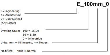
- 0 = Both extension lines suppressed
- 1 = First extension line suppressed
- 2 = Second extension line suppressed
- CL = Centreline extension lines
- Anno = Annotative (always as last modifier)
Text description of 3.5.1 Dimension Style Naming is available on a separate page.
Examples:
- A_50mm: Normal Architectural dimension for floor plans
- A_0mm Anno: Architectural dimension with Annotative property enabled
- A_50mm_0: Architectural dimension with no extension lines to dimension to grid lines
- E_1000m: Normal Engineering dimension for site plans with metres as base unit
- A_50mm_CL: Architectural dimension with centreline extension lines
- E_100mm_CL Anno: Annotative Engineering dimension with centreline extension lines
3.5.2 Multileader Style Naming
Multileader style usage should be uniform throughout each project drawing set.
Multileader style names have the following format:
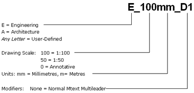
- D1 = Multileader with Detail Callout Block (D2, D3,etc. for alternate Detail callout Blocks)
- S = Multileader with Slot Callout Block
- C = Multileader with Circle Callout Block
- B = Multileader with Box Callout Block
- H = Multileader with Hexagon Callout Block
- T = Multileader with Triangle Callout Block
- Anno = Annotative
Text description of 3.5.2 Multileader Style Naming is available on a separate page.
Examples:
- A_50mm: Normal Mtext Multileader with Architectural font
- A_0mm Anno: Annotative Mtext Multileader with Architectural font
- E_50mm_D1: Normal Engineering Detail Callout Multileader
- E_0mm_C Anno: Annotative Engineering Circle Callout Multileader
3.6 Linetype and Hatch Standard
The appearance of linetypes in a drawing is determined by the system variables LTSCALE, PSLTSCALE, MSLTSCALE, and MEASUREMENT.
- The MEASUREMENT variable determines which linetype description file to use for linetype loading:
- The LTSCALE variable sets the global linetype scale factor.
- The PSLTSCALE controls linetype appearance in paper space.
- The MSLTSCALE controls the linetype appearance in model space in conjunction with the annotative scale (CANNOSCALE system variable in AutoCAD 2008+). When using MSLTSCALE, the variable LTSCALE should be set to between 0.5 and 1.
Note 1: Drawings must not contain linetypes, complex linetypes or hatch patterns other than those respectively defined in the ACADISO.LIN and ACADISO.PAT files supplied with the AutoCAD® based Autodesk products or other linetypes supplied by PWGSC.
Note 2: The linetypes and hatch patterns contained respectively in the ACAD.LIN and ACAT.PAT files should not be used because they are drawn to be used with imperial drawings. For consistent linetype appearance and plotting results, the required values for the variables are as follows:
- Final Drawings: Title sheet must be in paper space with multiple, variously scaled VIEWPORTS.
- MEASUREMENT = 1
- LTSCALE between 0.5 and 1.0 (See Note 3 below.)
- PSLTSCALE = 1 (On)
Note 3: The LTSCALE value should be set between 0.5 and 1.0 while printing in paper space depending on the size of the linetypes used in the drawing.
Do not set the linetype scale at the entity level. The Current Object Scale in the Linetype Properties dialog box (system variable CELTSCALE) must be set to 1.0 to ensure that the creation of new entities do not have entity-level linetype scaling.
For consistent hatch pattern plotting and scanning results, grey scale SOLID hatch patterns are not permitted on contract drawings.
3.7 Title Blocks and Graphic Scales
3.7.1 Title Block Set-up
Completed drawings must adhere to the following composition standard:
- Title block sheets must always be inserted in a layout (paper space) at 0,0,0 with scale factor of 1 and rotation angle of 0.
- Model space graphics must appear in the layout in correctly scaled VIEWPORTS.
- There must be only one (1) title block per layout.
- The title block is not to be exploded. Attributes must be used to enter title block information.
- No entities outside the title block perimeter.
3.7.2 Information in Title Blocks
All project drawings must be compiled on standard sheets and must be in accordance with the PWGSC corporate identity. The lead technologist for each project will coordinate the size of the sheet to be used and provide a standard title block and the content of the title block fields.
Each title block must contain the information below:
- Project name
- Address
- Drawing name, e.g. floor plan, building
- Measured or designed by and date
- Drawn by and date
- Approved by and date
- Project manager
- PWGSC project number
- Tender
- Drawing number
- Revision chart
- Consultant or CADD service identification
- North arrow
- Site plan (if pertinent)
3.7.3 Headings, Titles, and Graphic Scales
To facilitate scaling from reduced or enlarged reproductions, each plan, section, detail, elevation, profile, etc. on a completed drawing sheet shall be accompanied by a graphic scale. The graphic scale shall be located immediately below the pertinent heading on final plot.
3.8 Systems of Measurement and Preferred Scales
The International System of Units (S.I.) must be used to prepare all drawings. The unit for linear dimensioning is the millimetre, except where the scope of the drawing requires the use of the metre, such as in site plans. Integers shall indicate millimetres, e.g. 435, 4300. Decimal numbers with three decimal places shall indicate metres, e.g. 5.435, 4.300. All other dimensions and notations should be followed by the unit symbol.
Preferred Viewport Scale:
1:1 1:25 1:500
1:2 1:50 1:1000
1:5 1:100 1:2000
1:10 1:200 1:5000
1:20 1:250 1:10000
Document "PWGSC National CADD Standard" Navigation
- Date modified: